|
|
|
|
|
|
|
|
Dental Education Lecture: Design for Implant Placement
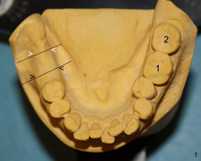
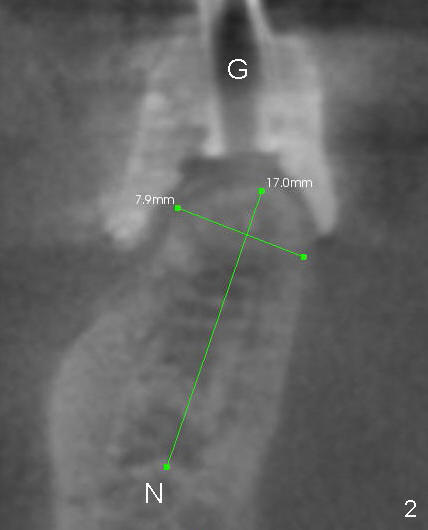
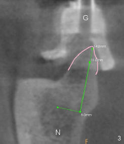
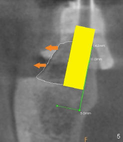
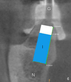
Mr. Ding has lost two molars as compared to the other side: 1,2 in Fig.1. Two implants are placed where two black lines indicate. As tooth beds move backward, the width appears to be narrower (compare the distance between black arrowheads with that between white arrowheads). Let us make cross sections through black lines to see what the bone looks like in these two molar areas. Fig.2 shows that bone in the first molar has enough width and height for placement of a 5x11 mm implant (I in Fig.6). However, in the 2nd molar region, the top of the bone (ridge) is quite narrow (pink outline in Fig.3) for placement of an implant of the equal size just mentioned above. On the top of the ridge is a special device to help place the implant in the right position so that the implant tooth can bite against the opposing tooth. The special device is called surgical guide (G). It appears that the ridge is not at the same line as the guide. How can we make them at the same line? We need to use bone expansion technique.
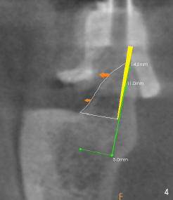
First, look at the vertical green line in Fig.3. The bone on its right is denser and more rigid (whiter in CT) than that on the left. When we drive a thin chisel along the vertical green line (yellow in Fig.4), the bone on the left (more pliable) starts to move left a little bit (arrows). Gradually we use thicker and thicker chisels, the bone moves more (Fig.5). We have enough space for implant placement on the top portion. Finally we make the hole deeper either by chisels or drills and place a proper-sized implant (I in Fig.6). Now the implant is aligned up with the guide on the top, whereas the implant is still far away from the underneath nerve (N).
With proper design, the real surgery is quite easy and successful.
Xin Wei, DDS, PhD, MS 1st edition 04/10/2011, last revision 01/19/2018